Omnibase Overview
This section documents the design and implementation of a custom holonomic base for FRIDA, a significant hardware upgrade intended to replace the DashGo differential drive platform currently in use.
Motivation
The DashGo platform, while functional, imposes constraints on the robot's navigation flexibility. Transitioning to a custom holonomic base offers several key advantages:
- Omnidirectional movement — the robot can translate in any direction without rotating, enabling smoother and more precise maneuvers in tight or dynamic indoor environments.
- Full mechanical ownership — being entirely designed and built by the team allows complete control over the platform's architecture, facilitating future improvements and adaptations tailored to competition requirements.
- Improved integration — custom electronics and mechanical structure allow a tighter integration between the base, the arm, and the rest of the robot's systems.
Mechanical Design
Wheel Selection: Mecanum vs Omni
An early design decision was whether to use mecanum wheels or omni wheels. Both achieve holonomic motion but differ in their trade-offs:
| Feature | Mecanum Wheels | Omni Wheels |
|---|---|---|
| Vibration & stability | Lower vibration, greater stability | More vibration |
| Space efficiency | Larger footprint (wheels offset 45°) | Smaller footprint |
| Push force | Greater in all directions | Lower |
| Max velocity | Moderate | Higher |
| Heavy load applications | Preferred | Less suitable |
| Cramped space navigation | Moderate | Better |
After evaluating competition requirements — particularly the need to carry loads and operate reliably — mecanum wheels were selected as the preferred choice.
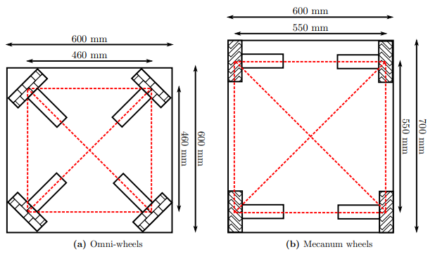
Space efficiency comparison between omni-wheels and mecanum wheels
CAD Design
The base structure uses 4040 aluminum extrusion profiles as the main chassis frame. Motors are mounted with custom-designed motor mounts that adapt the actuator attachment to the extrusion profile geometry.

Proof-of-concept CAD model of the omnibase
Actuator System: ODrive S1 + BLDC Motors
Each of the four wheels is driven by a brushless DC motor paired with an ODrive S1 motor controller, following a quasi direct drive (QDD) approach inspired by the OpenQDD project.
ODrive S1
The ODrive S1 is a compact, high-performance FOC (Field-Oriented Control) motor controller designed for robotics applications.
| Parameter | Value |
|---|---|
| DC bus voltage range | 12 V – 48 V (12S LiPo max) |
| Continuous phase current | 40 A (with heat spreader) |
| Continuous power output | 1600 W |
| PCB footprint | 66 mm × 50 mm |
| Mass | 35 g (55 g with screw terminals) |
| Communication | CAN (isolated, daisy-chain), UART, USB-C |
| Onboard absolute encoder | Yes — no homing required on startup |
| Control modes | Torque, velocity, position, trajectory |
Key features for this application:
- Galvanically isolated CAN bus with daisy-chain connectors (J16/J17), allowing all 4 S1s to share a single CAN bus to the main controller without ground loop issues.
- Onboard absolute encoder eliminates the need for homing routines when the robot powers on.
- Compact form factor (smaller than a credit card) makes it feasible to mount directly on the base chassis.
The four ODrive S1 units are connected in a CAN daisy-chain, all communicating with the central STM32H755 microcontroller using the CANSimple protocol.
Electronics & Control Architecture
The control PCB is the central hub of the omnibase, designed entirely by the team. It interfaces the main computer with the four motor controllers and onboard sensors.
Control PCB
The schematic was designed in EasyEDA (V1.0) by Ximena Trejo. Full schematic PDF available here.
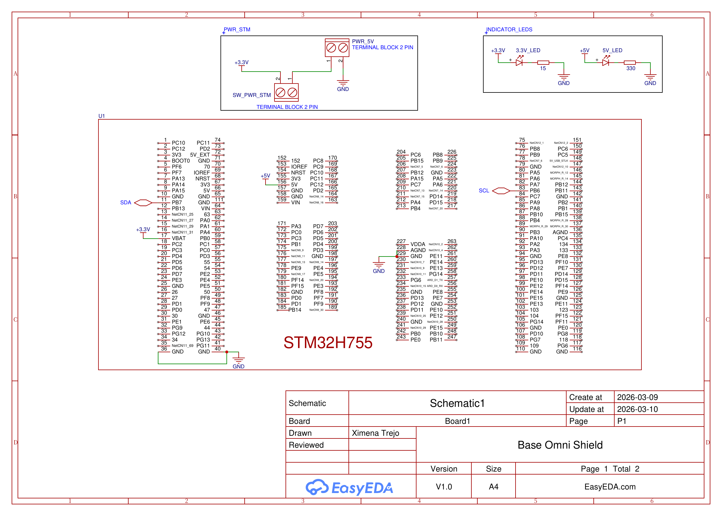
Base Omni Shield Rev 2 — Page 1: STM32H755 pinout
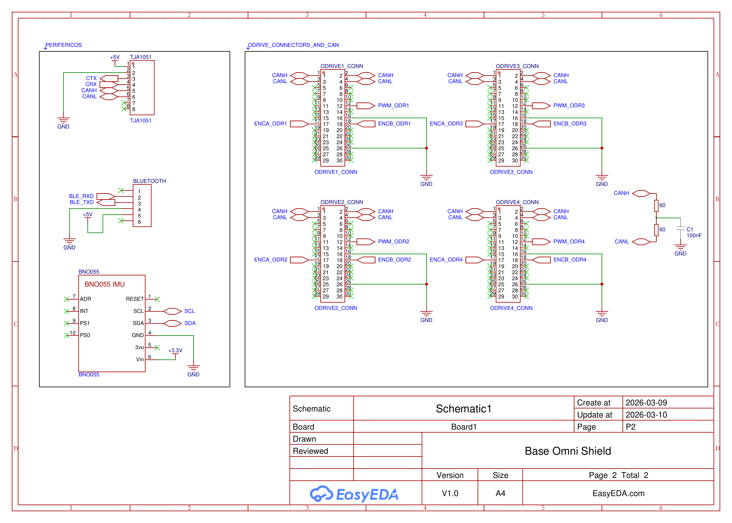
Base Omni Shield Rev 2 — Page 2: TJA1051, BNO055, BLE module and ODrive connectors
Key Components
| Component | Interface | Role |
|---|---|---|
| STM32H755 | — | Dual-core (Cortex-M7 + Cortex-M4) main microcontroller; handles CAN communication, odometry, and BLE |
| BNO055 | I2C (SCL/SDA) | 9-DOF IMU (accelerometer, gyroscope, magnetometer) for orientation and odometry fusion; powered at 3.3V |
| TJA1051 | CAN (CTX/CRX) | CAN bus transceiver; interfaces the STM32 CAN peripheral with the physical CAN bus to the 4 ODrive S1s; powered at 5V |
| BLE Module | UART (BLE_RXD/BLE_TXD) | Bluetooth Low Energy module for wireless gamepad connectivity; 6-pin connector, powered at 5V |
| ODrive connectors ×4 | 30-pin | Per ODrive: CANH/CANL, PWM, encoder channels A+B (ENCA/ENCB), GND |
| CAN termination | — | 2×60Ω resistors in series (= 120Ω) with 100nF capacitor to GND, per CAN bus standard |
| Power input | Terminal block 2-pin | PWR_5V input with power switch (SW_PWR_STM); 3.3V and 5V indicator LEDs onboard |
Communication Topology
[Main Computer]
      |
    [STM32H755]
      |  (CAN via TJA1051 — CANH/CANL)
      +——[ODrive S1 #1]  ← CANH, CANL, PWM, ENCA, ENCB
      +——[ODrive S1 #2]  ← CANH, CANL, PWM, ENCA, ENCB
      +——[ODrive S1 #3]  ← CANH, CANL, PWM, ENCA, ENCB
      +——[ODrive S1 #4]  ← CANH, CANL, PWM, ENCA, ENCB
                                    [120Ω + 100nF termination]

      + [BNO055]     (I2C — SCL/SDA)
      + [BLE Module] (UART — BLE_RXD/BLE_TXD)
The STM32H755 acts as the bridge between the high-level computer (running ROS 2) and the low-level motor controllers. It sends velocity/torque commands over CAN to each ODrive S1, and also routes PWM and encoder signals (ENCA/ENCB) per motor. IMU data from the BNO055 is read over I2C for odometry fusion.
The PCB was designed in EasyEDA (V1.0) by Ximena Trejo, created and updated on 2026-03-09/10.
Software & Repository
The firmware and ROS 2 integration code for the omnibase is maintained in the team's repository:
- GitHub: RoBorregos/home-custom-base
The repository includes: - STM32 firmware (CAN configuration, ODrive control functions, odometry) - ROS 2 nodes for base velocity commands and odometry publishing - Configuration and calibration utilities
References
- OpenQDD — Open-source Quasi Direct Drive Actuator
- ODrive S1 Datasheet
- Design Notes & Research Document
- K. Kanjanawanishkul, "Omnidirectional wheeled mobile robots: wheel types and practical applications," International Journal of Advanced Mechatronic Systems, vol. 6, no. 6, p. 289, 2015.
- Mo. Massoud et al., "Mechatronic Design and Path planning optimization for an Omni wheeled mobile robot for indoor applications," ICCTA, 2021.